New Regulation (EU) 2019/1781

RESOURCES

History

Since 2009, the European Union (EU) Commission has been working towards reducing energy consumption through legislation governing eco-design requirements for all energy-related products. At that time, it was estimated that there were about 85 million large electrical motors in operation throughout the EU, consuming around 65-70% of all energy used in industry.

To address this, the Commission enacted Regulation (EC) No 640/2009, which mandated that single-speed, three-phase, 50 Hz or 50/60 Hz squirrel cage induction motors for continuous duty, with 2 to 8 poles and power ratings between 0.75 kW and 375 kW, must meet specific efficiency levels.

According to that regulation:

  • Motors with a rated output of 7.5 to 375 kW had to meet the IE2 efficiency level by 16 June 2011.
  • Motors with a rated output of 0.75 to 375 kW had to meet the IE2 efficiency level by 1 January 2015.
  • From 1 January 2017, motors with a rated output of 0.75 to 375 kW had to meet the IE3 efficiency level, or the IE2 efficiency level if equipped with a variable speed drive.

Commission Regulation (EU) 2019/1781

Commission Regulation (EC) No 640/2009 remained in effect until 30 June 2021 and was subsequently repealed and replaced by Commission Regulation (EU) 2019/1781, which introduced updated requirements and came into force on 1 July 2021. This marked the implementation of the next phase of the directive, broadening the scope of the regulations to cover a wider range of electric motors. The prescribed changes are estimated to deliver roughly 10 TWh of energy savings by 2030, significantly reducing greenhouse gas emissions.

The new regulation expands the scope and introduces stricter efficiency requirements for motors and variable speed drives (VSDs). For the first time, it includes 60 Hz motors, brake motors with external brakes, and motors designed for use in hazardous environments. Additionally, VSDs with a rated voltage above 100V and up to and including 1000V AC are now included within the scope.

Here’s a brief outline of the new energy efficiency levels and requirements:

Energy Efficiency Requirements for Electric Motors:

IE2 Efficiency Level:

  • Motors with a rated output between 0.12 kW and 0.75 kW.

IE3 Efficiency Level:

  • Motors with a rated output from 0.75 kW to 1000 kW (inclusive).
  • Both 2-, 4-, 6-, and 8-pole motors are included.

IE4 Efficiency Level:

  • Motors with a rated output from 75 kW to 200 kW.

IE5 Efficiency Level:

  • This regulation encourages the development and market adoption of motors with even higher efficiencies (beyond IE4), although IE5 is not yet mandated.

Energy Efficiency Requirements for Variable Speed Drives:

IE2 Efficiency Level:

  • Variable speed drives with a rated output between 0.12 kW and 1000 kW.

Key Dates for Implementation:

As of 1 July 2021:

  • IE3 mandatory for motors with rated outputs between 0.75 kW and 1000 kW.
  • IE2 mandatory for motors with rated outputs between 0.12 kW and 0.75 kW.
  • IE2 mandatory for variable speed drives with rated outputs between 0.12 kW and 1000 kW.

A comprehensive table detailing all aspects of the New Regulation (EU) 2019/1781 – Step 1 for Motors, from 1 July 2021, is provided below:

Characteristics
Motors included in the regulation
Motors excluded from the regulation

Type of motor

Squirrel cage induction motor

Open and closed motors.

Wound rotors, DC, permanent magnet.

Motors specifically designed to operate wholly immersed in water.

Speed

Single speed motors, for fixed speed or VSD application.

Motors with multiple windings or with a switchable winding providing a different number of poles and speeds.

Mounting

Motors completely integrated into a product of which the energy performance can be tested independently from the product.

Motors completely integrated into a product of which the energy performance cannot be tested independently from the product.

Frequency

50 Hz, 60 Hz and 50/60 Hz

Others

Poles

2,4,6, 8

10 poles or higher

Rated Voltage

50 up to 1,000 V

Above 1,000 V

Rated Output

3 phase motors 0.75 – 1,000 kW must meet IE3

3 phase motors 0.12 kW – 0.75 kW (not incl.) must meet IE2

3 phase motors below 0.12 kW and above 1,000 kW

Duty Cycle

Continuous duty operation (S1),S3>= 80%, or S6>= 80%

Intermittent duty operations such as S2, S4, S5 etc.

Altitude

Up to 4000 m.a.s.l

Above 4000 m.a.s.l

Ambient air temperature

All motors -30°C to 60°C

Water cooled motors 0°C to 32°C

All motors below -30°C or above 60°C

Water cooled motors below 0°C or above 32°C

Cooling

Air: TEFC, TEAO, TEBC

Water: Coolant temperature at the inlet is between 0°C and 32°C

Air: TENV – Totally Enclosed Non-Ventilated Water:

Coolant temperature at the inlet is less than 0°C or higher than 32°C

Maximum operating temp

Up to 400˚C

Above 400˚C

Brake

Brake motors with external brake

Motors with an integrated brake where the brake is an integral part of the inner motor construction and can neither be removed nor supplied by a separate power source during the testing of the motor efficiency.

Area classification

Explosion-protected motors ‘Ex ec’, ‘Ex tb’, ‘Ex tc’, ‘Ex db’, ‘Ex dc’ or ‘Ex db eb’

Explosion protected motors for mining as defined in Annex 1, Point 1 of Directive 2014/34/EU

Increased safety motors of the Ex eb type

Variable Speed Drive Motors

When able to be equipped with a VSD must meet the same rules for motors without VSD.

Motors with integrated variable speed drive (compact drives) of which energy performance cannot be tested independently from the variable speed drive

Others


Motors specifically qualified for the safety of nuclear installations, as defined in article 3 of Directive 2009/71/EURATOM

Motors in cordless or battery operated equipment

Motors in hand-held equipment whose weight is supported by hand during operation

Motors in hand-guided mobile equipment moved while in operation

Motors with mechanical commutators

Motors specifically designed for electric vehicles

As of 1 July 2023:

  • IE4 mandatory for motors with rated outputs between 75 kW and 200 kW.
  • IE3 mandatory for explosion-proof motors and brake motors with rated outputs between 0.75 kW and 1000 kW.

All aspects of the New Regulation (EU) 2019/1781 – Step 2 for Motors, effective from 1 July 2023, are provided in the table below:

Characteristics
Motors included in the regulation
Motors excluded from the regulation

Type of motor

Squirrel cage induction motor

Open and closed motors.

Wound rotors, DC, permanent magnet. Motors specifically designed to operate wholly immersed in water.

Speed

Single speed motors, for fixed speed or VSD application.

Motors with multiple windings or with a switchable winding providing a different number of poles and speeds.

Mounting

Motors completely integrated into a product of which the energy performance can be tested independently from the product.

Motors completely integrated into a product of which the energy performance cannot be tested independently from the product.

Frequency

50 Hz, 60 Hz and 50/60 Hz

Others

Poles

2,4,6, 8 poles

10 poles or higher

Rated Voltage

50 up to 1,000 V

Above 1,000 V

Rated Output

3 phase motors 0.12 up to 0.75 kW (not included) must meet IE2.

3 phase motors 0.75 kW -1,000 kW must meet IE3 3 phase motors: 2, 4 and 6 pole, 75 kW up to 200 kW must meet IE4.

Single-phase: 0.12kW and above must meet IE2

3 phase motors below 0.12 kW and above 1,000 kW.

Duty Cycle

Continuous duty operation (S1),S3>= 80%, or S6>= 80%

Intermittent duty operations such as S2, S4, S5 etc.

Altitude

Up to 4000 m.a.s.l

Above 4000 m.a.s.l


Ambient air temperature

All motors: -30°C to 60°C

Water cooled motors 0°C to 32°C

All motors: below -30°C or above 60°C

Water cooled motors below 0°C or above 32°C

Cooling

Air: TEFC, TEAO, TEBC

Water: Coolant temperature at the inlet is between 0°C and 32°C

Air: TENV – Totally Enclosed Non-Ventilated

Water: Coolant temperature at the inlet is less than 0° C or higher than 32°C

Maximum operating temp

Up to 400˚C

Above 400˚C

Brake

Brake motors with external brake

0.12kW up to 0.75 kW (not incl.) must meet IE2

0.75 kW up to 1,000 Kw must meet IE3

Motors with an integrated brake where the brake is an integral part of the inner motor construction and can neither be removed nor supplied by a separate power source during the testing of the motor efficiency.

Area classification

Explosion-protected motors ‘Ex ec’, ‘Ex tb’, ‘Ex tc’, ‘Ex db’, ‘Ex dc’ or ‘Ex db eb’

0.12kW up to 0.75 kW (not incl.) must meet IE2

0.75 kW up to 1,000 Kw must meet IE3 Ex be

Equal or above 0.12 kW and equal or below 1,000 kW must meet IE2

Explosion protected motors for mining as defined in Annex 1, Point 1 of Directive 2014/34/EU

Variable Speed Drive Motors

When able to be equipped with a VSD must meet the same rules for motors without VSD.

Motors with integrated variable speed drive (compact drives) of which energy performance cannot be tested independently from the variable speed drive.

Others


Motors specifically qualified for the safety of nuclear installations, as defined in article 3 of Directive 2009/71/EURATOM.

Motors in cordless or battery-operated equipment.

Motors in hand-held equipment whose weight is supported by hand during operation.

Motors in hand-guided mobile equipment moved while in operation.

Motors with mechanical commutators.

Motors specifically designed for electric vehicles.


Specific Exclusions:

Excluded from the regulation are certain motor types and applications such as:

  • Motors specifically designed for hazardous environments.
  • Motors integrated into products where their energy performance cannot be tested independently.
  • Motors designed for variable speed operations that do not comply with fixed speed motor test conditions.

Variable Speed Drives (VSD)

From July 1st, 2021, Variable Speed Drives (VSDs) have also fallen within the remit of the EU 2019/1781 regulation. Initially, the regulation covers 3-phase standard VSDs with power ratings from 0.12 kW to 1000 kW and a rated voltage above 100V up to and including 1000V. The power losses of VSDs rated for operating with motors in this power range shall not exceed the maximum power losses corresponding to the IE2 efficiency level.

Major exemptions are:

  • VSDs integrated into a product whose energy performance cannot be tested independently from the product.
  • Regenerative drives.
  • Multiple AC-output drives.

The regulation is valid for:

  • New motors/VSDs placed on the market for the first time.
  • Replacement motors, as substitutes for identical motors integrated into products placed on the market until 1st July 2022 and specifically marketed for this purpose, do not have to meet the requirements of the new regulation and may be supplied according to (EC) 640/2009 until 1st July 2029.

Objective:

The regulation aims to improve the energy efficiency of electric motors and drives, thereby reducing energy consumption and greenhouse gas emissions in line with the EU’s broader climate and energy goals.

These requirements are intended to drive innovation in motor and drive technology, leading to more energy-efficient products on the market and ultimately contributing to the EU’s sustainability objectives.
Continue reading

Energy Efficiency Norms

RESOURCES

Electric Motors and Variable Speed Drives

Standards and legal requirements for the energy efficiency of low-voltage three-phase motors

Introduction

The conservative and responsible use of energy to save resources, to reduce the amount of CO2 emissions and to decrease energy costs is the order of the day. The electrical drive system plays a key role in this process. Electrical drives form the link between the electrical energy supply and the majority of mechanical processes, which require a large amount of energy. Machines driven by electrical motors consume 2/3 of all the electrical energy used in industry. If the old systems in German industry, commerce and public facilities, which have been running for decades, were all replaced by modern drive systems, this would result in annual energy savings of 38 billion kilowatt hours. Calculated for all of Europe, this figure would be 135 billion kilowatt hours. By using electronic speed control and energyefficient motors, Europe’s CO2 emissions could be reduced by 69 million tonnes.

This brochure describes the new standardised international efficiency classes for standard three-phase motors, the new measuring methods and the requirements stipulated by the European Regulation 640/2009 of the European Commission for energy efficiency in motors and drive systems. This brochure also offers an overview of some of the world-wide existing national legislation and addresses subjects like material composition and life cycle cost.

The brochure is written for users, original equipment manufacturers (OEM), machine manufacturers and motor and drive system manufacturers.

Efficiency Classes of Motors and Measuring Methods

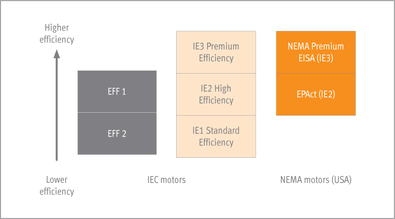
The term “efficiency” describes how efficiently an electric motor transforms electrical energy into mechanical energy. Previously in Europe, low voltage three-phase motors have been graded and marketed in three efficiency classes – EFF3, EFF2 and EFF1 – based on a voluntary agreement between motor manufacturers and the European Commission. This classification system is well proven and has now been adapted in many countries around the world. Unfortunately, other countries have also developed their own national systems, which are very different from the European system. That was the reason for the German motor manufacturers in ZVEI, with the support of their European neighbours, to develop an energy efficiency standard for the International Electrotechnical Commission (IEC). The objective was to have a common international standard that replaces all the different national systems. This project was successful and the objective has been met.

The new international standard, IEC 60034-30:2008, defines efficiency classes IE1, IE2 and IE3 for three-phase motors. This ensures a common international basis for the design and classification of motors as well as for national legislative activities. At the same time, the IEC developed improved methods for determining the efficiency of these motors.

The international standards IEC 60034-30:2008 (classification) and IEC 60034-2-1:2007 (measuring methods) have been adopted as European standards without any changes as EN 60034-30:2009 and EN 60034-2-1:2007. For the sake of simplicity, the following sections will refer to the IEC standards only.

Note: In these guidelines, “motors” always refers to low-voltage three-phase motors.

Previous efficiency classes of motors in Europe

In 1998, as part of the voluntary agreement between the European sector committee of Manufacturers of Electrical Machines and Power Electronics (CEMEP) and the European Commission, three efficiency classes were defined for the power range of 1.1 kW to 90 kW:

  • EFF3 = Motors with a low efficiency level
  • EFF2 = Motors with an improved efficiency level
  • EFF1 = Motors with a high efficiency level

New international standard for efficiency classes of motors (IE-code)

This voluntary agreement has since expired. However, the efficiency classes remain a registered European trademark. Use of the efficiency classes is based on a contractual licensing agreement between the participants in the voluntary agreement (motor manufacturers) and the license holder (CEMEP / Gimlec). This licensing agreement expired on 15 June 2011.

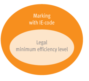
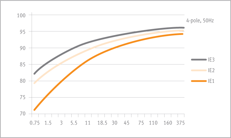
Standard IEC 60034-30:2008 defines the efficiency classes for low voltage three-phase motors with a power range from 0.75 kW to 375 kW. “IE” stands for “International Efficiency” and is combined with a number:

  • IE1 = Standard efficiency
  • IE2 = High efficiency
  • IE3 = Premium efficiency

The measurement of the efficiency levels is carried out according to the procedure described in IEC 60034-2-1:2007 (see section 1.3).

Important: The new efficiency class (IE-code) of a particular motor must be determined using the new measuring methods (section 1.3).

International standard efficiency level curves (IE-code).
Note: Excat values in section 1.6 efficiency classes.

New IEC measuring methods

The new measuring methods in accordance with IEC 60034-2-1:2007 (standard methods for determining losses and efficiency from tests) apply for all motors described by IEC 60034-1. These methods help to generate more exact data regarding stray load loss. The new standard replaces the previous European standard EN 60034-2:1996, which expired on 1 November 2010. Motors that are marked according to the new efficiency class system (IE-code) are required to be measured using the new measurement methods.

Comparison of old and new efficiency classes

The new international efficiency class system (IE-code) has an open numbering system. Compared to the old EFF efficiency classes, it is now easier to add future developments. In addition, there is a new class – IE3 – which did not exist in the old European EFF classification system. The scope has also been extended significantly; the new IE-code applies to a larger power range as well as for the 60 Hz classes e.g. in the USA. The main difference between the efficiency classes (EFF and IE) lies in the method used to determine them. In a direct comparison at the same motor, it is expected that the efficiency determined according to the new measuring method will be lower. For example, an 11 kW, 4-pole EFF1 motor with 91.0% efficiency is physically identical with a IE2 motor with 89.8% efficiency.

Efficiency classes

Scope of new IEC efficiency class system (IE-code)

The efficiency class system specified under IEC 60034-30 is valid for low voltage three-phase cage induction motors with the following specifications:
  • Rated voltage up to 1,000 V
  • Rated output between 0.75 kW and 375 kW
  • Either 2, 4 or 6 poles
  • Rated on the basis of continuous duty (S1) or intermittent periodic duty (S3) with cyclic duration factor of 80% or higher;
  • Capable of operating direct on-line
  • Rated for operating conditions in accordance with IEC 60034-1 (temperature, installation altitude, etc.)

Motors with flanges, feet and/or shafts with mechanical dimensions different from IEC 60072-1 are covered by this standard.

Geared motors and brake motors are covered by this standard, although special shafts and flanges may be used in such motors.

Some motors covered by this standard may be equipped with auxiliary devices. However, as long as these auxiliary devices are not an integral part of the motor construction, the determination of efficiency in all possible combinations is not practical. Determinations for efficiency of such modified standard motors shall be performed on basic motors without auxiliary devices installed.

The following are exceptions to the classification system:
 

  • Motors for short-time duty (S2) or switching operation (S3 < 80% to S10);
  • Motors that were solely designed for converter operation (VSD) in accordance with IEC 60034-25 as well as
  • Motors that have a highly specialised design customised for one particular application in such a way that it is not possible to measure the motor on its own (for example pump motors with wet rotors).

Efficiency classes IE1, IE2 and IE3

PN in kW
Number of poles

IE1, 50 Hz

IE2, 50 Hz

IE3, 50 Hz

2

4

6

2

4

6

2

4

6

0.75

72.1

72.1

70.0

77.4

79.6

75.9

80.7

82.5

78.9

1.1

75.0

75.0

72.9

79.6

81.4

78.1

82.7

84.1

81.0

1.5

77.2

77.2

75.2

81.3

82.8

79.8

84.2

85.3

82.5

2.2

79.7

79.7

77.7

83.2

84.3

81.8

85.9

86.7

84.3

3

81.5

81.5

79.7

84.6

85.5

83.3

87.1

87.7

85.6

4

83.1

83.1

81.4

85.8

86.6

84.6

88.1

88.6

86.8

5.5

84.7

84.7

83.1

87.0

87.7

86.0

89.2

89.6

88.0

7.5

86.0

86.0

84.7

88.1

88.7

87.2

90.1

90.4

89.1

11

87.6

87.6

86.4

89.4

89.8

88.7

91.2

91.4

90.3

15

88.7

88.7

87.7

90.3

90.6

89.7

91.9

92.1

91.2

18.5

89.3

89.3

88.6

90.9

91.2

90.4

92.4

92.6

91.7

22

89.9

89.9

89.2

91.3

91.6

90.9

92.7

93.0

92.2

30

90.7

90.7

90.2

92.0

92.3

91.7

93.3

93.6

92.9

37

91.2

91.2

90.8

92.5

92.7

92.2

93.7

93.9

93.3

45

91.7

91.7

91.4

92.9

93.1

92.7

94.0

94.2

93.7

55

92.1

92.1

91.9

93.2

93.5

93.1

94.3

94.6

94.1

75

92.7

92.7

92.6

93.8

94.0

93.7

94.7

95.0

94.6

90

93.0

93.0

92.9

94.1

94.2

94.0

95.0

95.2

94.9

110

93.3

93.3

93.3

94.3

94.5

94.3

95.2

95.4

95.1

132

93.5

93.5

93.5

94.6

94.7

94.6

95.4

95.6

95.4

160

93.8

93.8

93.8

94.8

94.9

94.8

95.6

95.8

95.6

200-375

94.0

94.0

94.0

95.0

95.1

95.0

95.8

96.0

95.8

Efficiency classes for 50 Hz in accordance with IEC 60034-30:2008

Efficiency classes for 60 Hz in accordance with IEC 60034-30: 2008

PN in kW
Number of poles

IE1, 60 Hz

IE2, 60 Hz

IE3, 60 Hz

2

4

6

2

4

6

2

4

6

0.75

77.0

78.0

73.0

75.5

82.5

80.0

77.0

85.5

82.5

1.1

78.5

79.0

75.0

82.5

84.0

85.5

84.0

86.5

87.5

1.5

81.0

81.5

77.0

84.0

84.0

86.5

85.5

86.5

88.5

2.2

81.5

83.0

78.5

85.5

87.5

87.5

86.5

89.5

89.5

3.7

84.5

85.0

83.5

87.5

87.5

87.5

88.5

89.5

89.5

5.5

86.0

87.0

85.0

88.5

89.5

89.5

89.5

91.7

91.0

7.5

87.5

87.5

86.0

89.5

89.5

89.5

90.2

91.7

91.0

11

87.5

88.5

89.0

90.2

91.0

90.2

91.0

92.4

91.7

15

88.5

89.5

89.5

90.2

91.0

90.2

91.0

93.0

91.7

18.5

89.5

90.5

90.2

91.0

92.4

91.7

91.7

93.6

93.0

22

89.5

91.0

91.0

91.0

92.4

91.7

91.7

93.6

93.0

30

90.2

91.7

91.7

91.7

93.0

93.0

92.4

94.1

94.1

37

91.5

92.4

91.7

92.4

93.0

93.0

93.0

94.5

94.1

45

91.7

93.0

91.7

93.0

93.6

93.6

93.6

95.0

94.5

55

92.4

93.0

92.1

93.0

94.1

93.6

93.6

95.4

94.5

75

93.0

93.2

93.0

93.6

94.5

94.1

94.1

95.4

95.0

90

93.0

93.2

93.0

94.5

94.5

94.1

95.0

95.4

95.0

110

93.0

93.5

94.1

94.5

95.0

95.0

95.0

95.8

95.8

150

94.1

94.5

94.1

95.0

95.0

95.0

95.4

96.2

95.8

185-375

94.1

94.5

94.1

95.4

95.4

95.0

95.8

96.2

95.8

Efficiency classes for 60 Hz in accordance with IEC 60034-30:2008

EuP Directive and EU Motor Regulation

The European Union set the environmental goal of reducing greenhouse gas emissions by 20% by the year 2020. Early measures taken to reach this goal were the ban on incandescent light bulbs and the specifications for the reduction of standby losses. The legal basis for these measures is the EuP Directive (2005/32/EC), adopted on 6 July 2005, which defines the requirements for the ecodesign of energy-using products. The EuP Directive forms the basis for numerous product-related directives. On 21 October 2009, a new version of this directive went into effect (2009/125/EC). This new directive expanded the requirements to include the ecodesign of energy-related products (ErP – Energy-Related Products). Germany’s national version of this directive is the Energy-Using Products Act (Energiebetriebene- Produkte-Gesetz – “EBPG”), which is often referred to as the “ecodesign directive”.

Commission Regulation (EC) 640 / 2009

Commission Regulation 640/2009, adopted on 22 July 2009, specifies the requirements regarding the ecodesign of electric motors and the use of electronic speed control (VSD). These requirements also apply when these devices are integrated in other products (e.g. machines).

Scope and exceptions

The scope of the EuP Motor Regulation is more limited than that of IEC 60034-30. Both include low voltage three-phase cage-induction motors for 50 Hz or 50/60 Hz with the following properties:
 

  • Rated voltage up to 1,000 V
  • Rated output between 0.75 kW and 375 kW
  • Either 2, 4 or 6 poles
  • Rated for continuous duty

The differences between the EuP Motor regulation and IEC standard lie in the exceptions and in the additional operating mode, S3 (cyclic duration factor ≥ 80%).

The following are exempted from the EuP Motor Regulation:
 

  • Motors designed to operate wholly immersed in a liquid
  • Motors completely integrated into a product for which the energy efficiency cannot be measured independently of the product
  • Motors that are specially designed for operation under the following conditions:
    • At altitudes exceeding 1,000 meters above sea level
    • Where ambient air temperatures exceed 40°C
    • At maximum operating temperatures above 400°C
    • Where ambient air temperatures are less than -15°C for any motor or less than 0°C for a motor with air cooling;*
    • Where the water coolant temperature at the inlet to a product is less than 5°C or exceeding 25°C
    • In potentially explosive atmospheres as defined in Directive 94/9/EC of the European Parliament and the European Council (3)
  • Brake motors

* Note: The European Commission has confirmed that the word “air cooling” is a typing mistake and should be corrected into “water cooling”. The current text of the directive is valid until further notice.

Requirements and schedule

The individual requirements will come into effect in accordance with the following schedule:
 

  • From 16 June 2011, motors placed for the first-time on the market shall have a minimum efficiency class of IE2.
  • From 1 January 2015: motors with a rated output between 7.5 – 375 kW shall have a minimum efficiency class of IE3, or minimum IE2 if they are operated/equipped with electronic speed control (VSD).
  • From 1 January 2017: motors with a rated output between 0.75 – 375 kW shall have a minimum efficiency class of IE3, or minimum IE2 if they are operated/equipped with electronic speed control (VSD).

Electronic speed control is carried out using a frequency converter (VSD) that adjusts the speed of the motor – and therefore the power produced – based on the energy needed. See section 3 for the detailed implementation strategy for this schedule.

Scope of standard and directive

Standards function as recommendations that can be observed voluntarily by anyone. Standards are not legally binding, however they may become so as a result of legal regulations imposed by lawmakers or through contracts in which compliance is mandatory. They often serve to clarify undefined legal terms – for example the term “state of the art” – thereby gaining legal significance.

The standard IEC 60034-30:2008 defines efficiency classes for motors, thereby creating a common international guideline. However, the standard itself does not specify whether motors are required to comply with a particular minimum efficiency class. This is specified by the applicable national laws and directives. In Europe, Commission Regulation 640/2009 specifies the minimum requirements.

Please note that the scope of the EU Motor Directive (section 2.2) is more limited than that of IEC 60034-30.

 
Which motor falls under which scope?
Standard
IEC 60034-30: 2008
Class markings for IE1, IE2, IE3
EuP directive/
Regulation 640/2009
Legal minimum requirement

1

Standard three-phase induction motor
0.75 – 375 kW, 2, 4, 6 pole,
continuous duty, 50 Hz or 50/60 Hz
(Note: Also applies if the motor
is integrated in a machine.)
Yes
Note: Also S3 operating mode
(cyclic duration factor ≥80%)
Yes

2

Standard three-phase induction motor
with auxiliary devices (shaft seals,
back-stops, speed sensors etc.)
0.75 – 375 kW, 2, 4, 6 pole,
continuous duty, 50 Hz or 50/60 Hz
(Note: Measurement of efficiency
without auxiliary devices)
Yes
Note: Also S3 operating mode
(cyclic duration factor ≥80%)
Yes

3

Geared motors

Yes

Yes

4

Explosion-protected motors

Yes

No

5

Brake motor: A motor equipped
with an electro-mechanical brake
unit operating directly on the
motor shaft without couplings.

Yes

No

6

Motors completely integrated
into a machine (for example pump,
ventilators, gear or compressor)
of which the efficiency cannot be tested
independently from the machine.

No

No

7

Other types of motors
(e.g. permanent magnet motors,
pole-changing motors, motors for
switching operation e.g. servomotors)

No

No

Comparison of scope of IEC/EU Motor Regulation

Efficiency marking on motor

Each motor must be equipped with a rating plate. The data on the rating plate is specified in standard IEC 60034-1. This includes the efficiency level of the motor ç at 100% rated load only. The Motor Regulation also requires the indication of the efficiency level at 75% and 50% rated load.

ZVEI is of the opinion that it is sufficient to indicate the efficiency level at 100% rated load on the rating plate only, as described in IEC 60034-1. It is considered to be sufficient to list the efficiency level at 75% and 50% rated load in the documentation of the product only. ZVEI has requested clarification from the European Commission. Note that the current text of the regulation remains valid until further notice.

Implementing the Requirements of the EU Motor Regulation

The manufacturer or an authorised representative must ensure that the motors conform with the requirements of Commission Regulation 640/2009. Just as for other European product requirements (“CE Directives”) the date of the “first-time placing on the market,” and in certain cases, the “putting into service” of products determine the effectiveness of these requirements.

The following sub-clauses 3.1 to 3.6 are ZVEI positions that have been prepared based on legal requirements and European Commission publications regarding CE Directives.

Date of first-time placing on the market

Motors that were placed on the market before the deadline of 16 June 2011 may continue to be sold after the deadline. They may also be put into service and operated in accordance with the regulations in effect before that deadline.

Practical example
Manufacturer A, identified by name on or near the product, may place motors with an efficiency level lower than efficiency class IE2 in accordance with the scope of Directive 640/2009 on the market until 15 June 2011. These motors are considered to have been placed on the market legally if they have been transferred to another legal person (e.g. distributors, LTD sales company of the manufacturer) before this date. They may then be resold, put into service and used after the deadline of 16 June 2011.

Motors integrated into other products

Motors that were placed for the first-time on the market before the deadline of 16 June 2011 may also be integrated into other products after the deadline.

Practical example
A machine (e.g. compressor, pump) contains an integrated motor of efficiency class IE1 in accordance with Directive 640/2009. The manufacturer of this motor is identified by name on or near the integrated motor. The motor was first-time placed on the market before 16 June 2011 in accordance with the law. The machine with the integrated motor of efficiency class IE1 may be placed on the market and used even after the deadline of 16 June 2011.

By including motors that are integrated into other products, and which therefore are not first-time placed on the market as motors, the regulation prevents circumvention of the law by the purchase of imported products (e.g. machines).

Practical example
A pump, in this case a finished product that contains a motor in accordance with the scope of Directive 640/2009, is imported into the European community. The integrated motor must comply with the requirements of Directive 640/2009. In this case, this is the first time the motor is being placed on the European market as an integrated motor.

Spare motors

The regulation does not allow any exception for spare motors. Please note the requirements listed in sub-clause 3.1 “Date of first-time placing on the market”.

Practical example
A motor of efficiency class IE1 may not even be placed on the market (for the first time) as a spare part after the deadline of 16 June 2011 in accordance with the scope of Directive 640/2009.

Consignment stock

There are different contracts for consignment stock. In practice, consignment stock refers to products held in the stock of a supplier or a service provider that belongs to the company of the customer (buyer).
The products remains the property of the supplier until the customer removes it from the stock. The delivery date is considered to be the date upon which the product is removed from the stock. The invoice will be based on this date. However, in the act of placing the energy-using product in consignment stock (subject to or free of charge), the supplier is performing a first-time placing on the market of the product in question.

Practical example
Motors covered by the scope of Directive 640/2009 with an efficiency level lower than efficiency class IE2 that have been placed in consignment stock before the deadline of 16 June 2011, allowing the customer unlimited power of disposal, may be removed from the stock and used by the customer after the appointed date.

Putting motors with variable speed drive into service

Motors of efficiency class IE2 may also be placed on the market after the deadline of 1 January 2015, provided that they comply with certain conditions. These conditions stipulate that the manufacturer or an authorised representative must display a notice on the motor itself and in the product information that indicates that the motor in question may only be operated using electronic speed control, in accordance with the EuP Motor regulation. For motors of class IE2 that have been placed on the market before 1 January 2015 (2017), see sub-clause 3.1 “Date of first-time placing on the market”.

Exports outside the European economic area

The following are not cases of placing products on the market in the sense of the ErP Directive 2009/125/ EG* and its implementing regulations:

  • if the product is exported from a manufacturer in a member state to a third country outside the European economic area (EEA).
  • if a manufacturer’s product is transferred to an exporter (traders or machine manufacturers) that then exports it outside the EEA independently or as an integrated component.

* Replacement for the preceding EuP Directive 2005/32/EC

Practical example

  • A manufacturer based in the European economic area (EEA) can produce and distribute motors of class IE1 within the scope of regulation 640/2009 even after 16 June 2011 insofar as these motors are exclusively intended for export outside the EEA. These motors cannot be labelled with the CE marking.
  • A manufacturer in the European economic area (EEA) of machines integrates electric motors into its machines and exports these exclusively to countries outside the EEA. The integrated motors do not need to comply with regulation 640/2009 and other CE Directives and must not be labelled with the CE mark.

Note: It it to be taken care that these motors are sold for use outside of the European economic area only.

Market surveillance

Market surveillance is the responsibility of the EU member states. The member states shall designate the authorities responsible for market surveillance and specify the necessary tasks, powers and organisational arrangements. In Germany, market surveillance is the responsibility of the federal state authorities. The German Federal Institute for Materials Research and Testing (Bundesanstalt fr Materialforschung und -prfung – “BAM”) is responsible for coordinating the exchange of information between the federal state authorities in charge of market surveillance and the other EU member states. BAM supports the federal state authorities in the development of their surveillance concept and in the inspection of the effectiveness of their market surveillance methods.

International Regulations for Energy-Efficient Motors

World-wide there are various national regulations for the use of energy-efficient motors. Some of these are currently in effect and some are still in progress. The table below provides an overview of the regulations in important industrial countries. We cannot guarantee that this table is complete, as this topic is currently being developed rapidly.

Australia: The E3 Program – Improving Our Energy Efficiency
Brazil: INMETRO: Instituto Nacional de Metrologia
China: 中国标准化研究院: China National Institute of Standardization
中国能效标识网: China Energy Efficiency Label Network
Canada: Natural Resources Canada / Ressources naturelles Canada
Korea: 산업통상자원부: Ministry of Trade, Industry and Energy
Mexico: SENER: Secretaría de Energía
Switzerland: BFE: Bundesamt für Energie
South Africa: SABS – South African Bureau of Standards
SABS – The Rotating Machines Laboratory
U.S.A.: NEMA – National Electrical Manufacturers Association:
NEMA Premium Motors

Material Composition of Motors

The ecodesign directive also affects the material composition of the relevant products. A study sponsored by the European Commission determined that it is the use phase rather than the manufacturing phase that determines the environmental characteristics of a particular motor. The European sector committee of Manufacturers of Electrical Machines and Power Electronics (CEMEP) determined average values for the material composition. Tables 5 through 7 show the most important materials used to manufacture motors in power ranges 1.1 kW, 11 kW and 110 kW in efficiency classes IE1 and IE2.

Typical material composition of a 1.1 kW motor in class IE1 or IE2

 
1.1 kW motor, IE1
1.1 kW motor, IE2

Average kg/per kW

Tolerance

Average kg/per kW

Tolerance

Electrical steel

5.40

8.00

Other steel 1.50

1.60


Cast iron*

2.50

0.0 – 5.0

2.50

0.0 – 5.0

Aluminium*

1.70

0.5 – 2.5

2.00

0.5 – 4.0

Copper

1.24

1.90

Insulation material

0.05

0.05

Packaging material

1.00

1.00

Impregnating resin

0.30

0.30

Paint/Colour

0.10

0.10

Typical material composition of a 11 kW motor in class IE1 or IE2

 
11 kW motor, IE1
11 kW motor, IE2

Average kg/per kW

Tolerance

Average kg/per kW

Tolerance

Electrical steel

3.60

4.80

Other steel

0.95

1.00

Cast iron*

1.30

0.0 – 2.0

1.30

0.0 – 2.0

Aluminium*

0.90

0.2 – 1.5

1.00

0.25 – 1.8

Copper

0.64

0.90

Insulation material

0.02

0.02

Packaging material

0.90

0.90

Impregnating resin

0.10

0.10

Paint/Colour

0.05

0.05

Typical material composition of a 110 kW motor in class IE1 or IE2

 
110 kW motor, IE1
110 kW motor, IE2

Average kg/per kW

Tolerance

Average kg/per kW

Tolerance

Electrical steel

3.10

3.60

Other steel

0.67

0.70

Cast iron*

3.00

3.00

Aluminium*

0.18

0.20

Copper

0.54

0.60

Insulation material

0.01

0.01

Packaging material

0.50

0.50

Impregnating resin

0.05

0.05

Paint/Colour

0.01

0.01

*The tolerances for cast iron and aluminium are given because both materials
are suitable for use in certain parts of the motors (e.g. the housing).

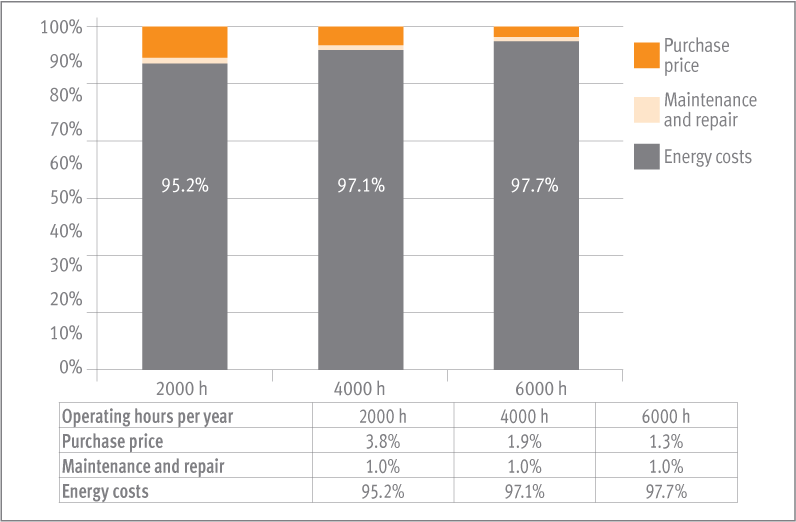
The amount of material used increases with higher efficiency classes. Motors of efficiency class IE3 require a much greater use of materials than motors of efficiency class IE2. The purchasing price also increases for higher efficiency classes. In terms of the cost of the entire life cycle of the unit, in spite of the higher purchasing price, these motors pay for themselves within a relatively short time (see section 6).

Life Cycle Cost Analysis

The increased purchasing price for energy-efficient drive systems is often quickly recovered due to the total savings in energy costs. For this reason, it is important to conduct a life cycle cost analysis (LCC analysis) before making investment decisions in order to evaluate the total economic benefits of a particular drive system.
A very simple LCC analysis can be carried out for the motor as a component. The energy costs during the use phase are significant, leading to relatively short pay-back periods.

LCC analysis, 11 kW motors, life cycle 15 years, IE2
(Source: Preparatory Studies, EUP- Lot 11 Motors

References
 

  • IEC 60034-1:2010, Rotating electrical machines – Part 1: Rating and performance

  • IEC 60034-2-1:2007, Rotating electrical machines – Part 2-1: Standard methods for determining losses and efficiency from tests

  • IEC 60034-30:2008, Rotating electrical machines – Part 30: Efficiency classes of single-speed, threephase, cage-induction motors (IE-code)

  • Guide to the implementation of directives based on the new approach and the global approach, ISBN 92-828-7449-0

  • Preparatory Studies, EUP- Lot 11 Motors, Aníbal T. de Almeida, Fernando J. T. E. Ferreira, João Fong, Paula Fonseca, ISR- University of Coimbra (18 February 2008)

  • Directive 2005/32/EC establishing a framework for the setting of ecodesign requirements for energyusing products

  • Directive 2009/125/EC establishing a framework for the setting of ecodesign requirements for energy-related products

  • Commission Regulation (EC) 640/2009 of 22 July 2009 implementing Directive 2005/32/EC of the European Parliament and of the Council with regard to ecodesign requirements for electric motors

Continue reading

Permissible Radial Loads

RESOURCES

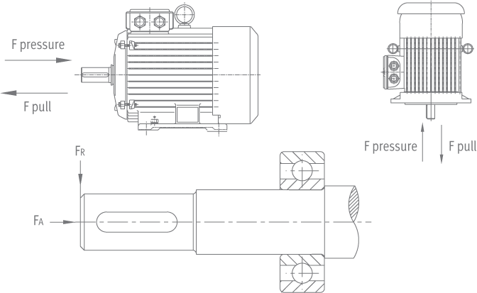
The following table gives the permissible radial force in Newton, assuming zero axial force and standard ball bearings. In case of higher radial force than given in the table an reinforced bearing should be ordered. The values are based on normal conditions at 50Hz and calculated at 20.000 working hours for the 2-pole motors and 40.000 working hours for the 4p, 6p, 8p motors.
For 60Hz the value must be reduced by 10%.
For two speed motors, the values have to be based at the higher speed.

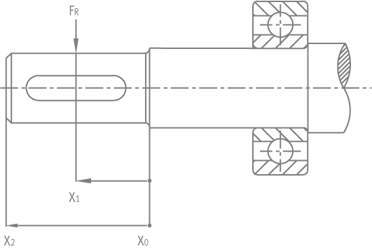
In order to calculate the actual force on a motor shaft, we use the following formula:

Where:

M: is the rated torque of the motor
D: is the pulley diameter [m]
K: belt tension factor. K=2.2 – 3 for V-belts or flat belts.

Frame size
Pole
Permissible radial load
 
Frame size
Pole
Permissible radial load
 
Frame size
Pole
Permissible radial load
 
 
At Xo
At X1/2
At Xmax
 
 
At Xo
At X1/2
At Xmax
 
 
At Xo
At X1/2
At Xmax
56
2/4
250
180
100
132
2
2,160
1,900
1,690
250
2
5,260
4,660
4,180
63
2/4
360
300
230
 
4
2,140
1,910
1,720
 
4
5,180
4,590
4,120
71
2/4/6
470
400
320
 
6
2,450
2,190
1,970
 
6
5,890
5,220
4,690
80
2
640
590
540
 
8
2,700
2,410
2,180
 
8
6,520
5,780
5,190
 
4
640
580
540
160
2
2,790
2,470
2,210
280
2
5,500
5,000
4,600
 
6
730
660
610
 
4
2,770
2,450
2,190
 
4
5,650
5,150
4,700
 
8
800
730
670
 
6
3,150
2,790
2,490
 
6
6,800
6,300
5,700
90
2
730
660
610
 
8
3,480
3,080
2,750
 
8
7,700
7,200
6,500
 
4
720
660
600
180
2
3,130
2,790
2,510
315
2
5,500
5,000
4,600
 
6
820
750
680
 
4
3,070
2,740
2,470
 
4
6,200
5,700
5,200
 
8
910
820
750
 
6
3,500
3,120
2,810
 
6
7,350
6,700
6,150
100
2
1,020
910
830
 
8
3,870
3,450
3,110
 
8
8,350
7,600
6,950
 
4
1,010
910
820
200
2
4,160
3,730
3,390
355
2
12,500
12,000
11,750
 
6
1,150
1,030
940
 
4
4,130
3,700
3,360
 
4
28,300
25,860
14,290
 
8
1,270
1,140
1,030
 
6
4,690
4,210
3,820
 
6
32,400
29,600
16,350
112
2
1,480
1,350
1,240
 
8
5,190
4,650
4,220
 
8
35,660
32,580
18,000
 
4
1,470
1,340
1,230
225
2
4,700
4,260
3,890
400
2


6
1,680
1,530
1,410
 
4
4,620
4,080
3,650
 
4
33,730
31,140
19,280
 
8
1,850
1,680
1,550
 
6
5,250
4,630
4,150
 
6
38,610
35,650
22,070


8
5,820
5,130
4,590
 
 
8
42,500
39,240
24,290

The following table gives the permissible axial forces in Nt, assuming zero radial force. In case axial & radial forces apply together, please consult our engineering department. For higher axial forces, it is possible to execute the motors with angular contact bearings. The values are based for normal conditions at 50Hz and calculated at 20.000 working hours for 2-pole motors and 40.000 working hours for 4p, 6p, 8p motors. At 60Hz, the values must be decreased by 10%. For double speed motors the values have to be based at the higher speed.
KA-A motors have their own table for permissible axial loads, since angular contact bearings are standard for this series.

Maximum axial force [N]
 
Maximum axial force [N]
 
Maximum axial force [N]
Frame
size
Pole
B3
Push
B3
Pull
V1
Push
V1
Pull
Frame
size
Pole
B3
Push
B3
Pull
V1
Push
V1
Pull
Frame
size
Pole
B3
Push
B3
Pull
V1
Push
V1
Pull
56
2/4
200
200
230
180
132
2
1,500
1,500
1,620
1,430
250
2
3,100
3,100
3,940
2,260
63
2/4
250
250
260
230
 
4
1,780
1,780
1,970
1,610
 
4
3,900
3,900
5,000
2,800
71
2/4/6
270
270
290
255
 
6
1,820
1,820
2,000
1,660
 
6
4,450
4,450
5,570
3,230
80
2
380
380
400
360
 
8
1,920
1,920
2,100
1,760
 
8
4,980
4,980
6,380
3,580
 
4
470
470
490
450
160
2
1,650
1,650
1,950
1,350
280
2
5,300
3,100
6,500
2,100
 
6
590
590
620
560
 
4
2,100
2,100
2,470
1,720
 
4
6,300
4,400
7,800
3,000
 
8
620
620
650
595
 
6
2,450
2,450
2,800
2,050
 
6
6,700
4,300
7,900
2,900
90
2
440
440
470
410
 
8
2,650
2,650
3,050
2,210
 
8
7,100
5,020
9,100
3,520
 
4
550
550
600
510
180
2
2,100
2,100
2,450
1,720
315
2
5,900
3,800
8,000
2,000
 
6
620
620
680
460
 
4
2,600
2,600
3,200
2,000
 
4
7,100
5,100
10,700
3,150
 
8
640
640
700
580
 
6
2,900
2,900
3,510
2,280
 
6
7,600
5,800
11,800
3,500
100
2
610
610
670
570
 
8
3,170
3,170
3,780
2,550
 
8
8,100
6,300
12,500
4,400
 
4
750
750
840
710
200
2
2,400
2,400
2,940
1,840
355
2
6,100
1,850
14,000
800
 
6
880
880
970
820
 
4
3,120
3,120
3,850
2,390
 
4
9,800
3,900
18,300
2,500
 
8
895
895
970
845
 
6
3,480
3,480
4,350
2,610
 
6
10,500
4,700
20,700
3,500
112
2
1,220
1,220
1,300
1,170
 
8
3,950
3,950
4,810
3,090
 
8
12,500
6,000
21,500
3,600
 
4
1,440
1,440
1,520
1,370
225
2
2,720
2,720
3,420
2,020
400
2


6
1,650
1,650
1,740
1,580
 
4
3,480
3,480
4,370
2,590
 
4
11,200
3,900
18,500
1,600
 
8
1,780
1,780
1,880
1,710
 
6
3,890
3,890
5,040
2,820
 
6
12,500
4,800
19,500
2,200


8
4,330
4,330
5,330
3,330
 
 
8
12,800
4,950
21,500
2,900

Continue reading

Mounting Arrangements

RESOURCES

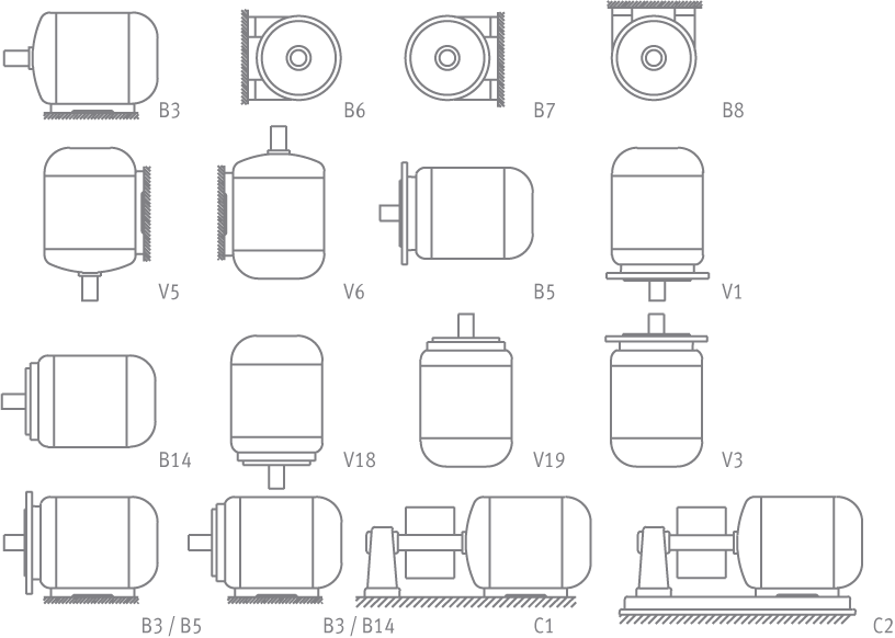
The most commonly used mounting arrangements are shown in the table below.
Other mounting arrangements are available on request.

Mounting arrangement of each motor is stated on the name plate.
Standard motors ordered in basic mounting arrangements (universal mounting arrangements) IM B3, IM B5, IM B14 can also be used in the following mounting positions:

IM B3 in:   IM B6, IM B7, IM B8, IM V5 or IM V6.
IM B5 in:   IM V1 or IM V3. [with the exception of special designs where bearings series 7000 are used for vertical mountings V1 & V3]
IM B14 in:   IM V18 or IM V19.

Please be aware that large 315 & 355 frame flange-mounted motors may not be able to support the weight adequately. Therefore, it is advisable to opt for B35 (foot & flange) mounted motors instead.

Continue reading

Connecting Diagrams

RESOURCES

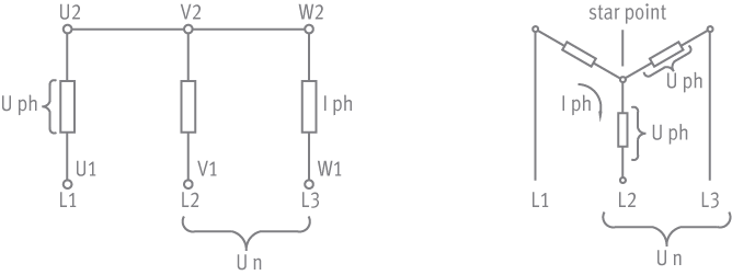
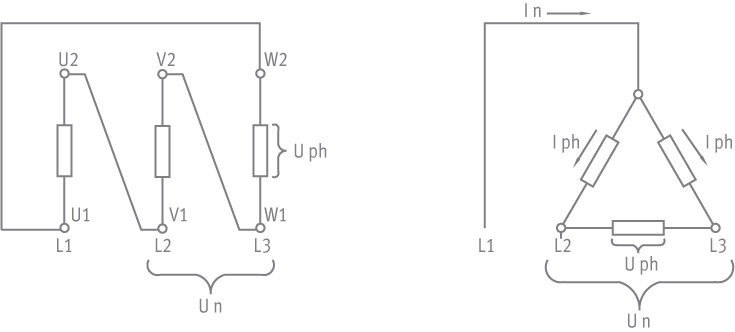
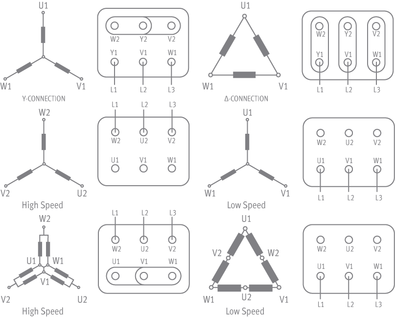
Y or Star connection

Connecting together the W2, U2, V2 terminals (star point) and connecting to the mains the U1, V1, W1 terminals a star connection is obtained.

The phase current Iph and the phase voltage Vph are as following:

Iph = In
Vph = Vn/3

Where:

In:   the line current
Vn:   the line voltage

Δ or Delta connection

Connecting the end of each winding to the beginning of the next winding a delta connection is obtained.
The phase current Iph and the phase voltage Vph are as following:

Iph=In/3
Vph= Vn

Star-Delta starting

Continue reading

IEC 60034-30-1 Standard

RESOURCES

IEC 60034-30-1 standard

On efficiency classes for low voltage AC motors

Standard IEC/EN 60034-30-1 on efficiency classes of line operated AC motors was published by the International Electrotechnical Commission (IEC) on March 6, 2014.This IEC standard is concerned with the global harmonization of energy efficiency classes for electric motors. Compared with IEC/EN 60034-30: 2008, it significantly expands the range of products covered with the inclusion of 8-pole motors and introduces IE4 efficiency performance class for electric motors. All technical constructions of motors are covered as long as they are rated for direct on-line operation. Whereas the previous edition covered only three-phase products, the new standard also includes single-phase motors, as well as line-start permanent magnet motors.

Efficiency classes defined by IEC/EN 60034-30-1: 2014

The standard defines four IE (International Efficiency) efficiency classes for single speed electric motors that are rated according to IEC 60034-1 or IEC 60079-0 (explosive atmospheres) and designed for operation on sinusoidal voltage.

Super-Premium efficiency IE4
Premium efficiency IE3
High efficiency IE2
Standard efficiency IE1

An IE5 level is envisaged for a future revision, with the goal of further reducing losses by some 20% relative to IE4.

Motors covered by the standard

The new standard covers a wider scope of products. The power range has been expanded to cover motors from 120 W to 1000 kW. All technical constructions of electric motors are covered as long as they are rated for direct on-line operation. The coverage of the new standard includes:

  • Single speed electric motors (single and three phase), 50 and 60 Hz
  • 2, 4, 6 or 8 poles
  • Rated output PN from 0.12 kW to 1000 kW
  • Rated voltage UN above 50 V up to 1 kV
  • Motors, capable of continuous operation at their rated power with a temperature rise within the specified insulation temperature class
  • Motors, marked with any ambient temperature within the range of -20°C to +60°C
  • Motors, marked with an altitude up to 4000 m above sea level

Motors excluded from the standard

The following motors are excluded from IEC/EN 60034-30-1

  • Single-speed motors with 10 or more poles or multi-speed motors
  • Motors completely integrated into a machine (for example, pump, fan or compressor) that cannot be tested separately from the machine
  • Brake motors, when the brake can not be dismantled or separately fed

What is the classification based on

The efficiency levels defined in IEC/EN 60034-30-1 are based on the low uncertainty test methods specified in IEC 60034-2-1, which has been updated to edition 2.0, 2014-06.

Minimum 50 Hz efficiency values defined in IEC/EN 60034-30-1:2014 (based on test methods specified in IEC 60034-2-1:2014)

PN in kW
Number of poles

IE1

IE2

IE3

IE4

2

4

6

8

2

4

6

8

2

4

6

8

2

4

6

8

0.12

45.0

50.0

38.3

31.0

53.6

59.1

50.6

39.8

60.8

64.8

57.7

50.7

66.5

69.8

64.9

62.3

0.18

52.8

57.0

45.5

38.0

60.4

64.7

56.6

45.9

65.9

69.9

63.9

58.7

70.8

74.7

70.1

67.2

0.20

54.6

58.5

47.6

39.7

61.9

65.9

58.2

47.4

67.2

71.1

65.4

60.6

71.9

75.8

71.4

68.4

0.25

58.2

61.5

52.1

43.4

64.8

68.5

61.6

50.6

69.7

73.5

68.6

64.1

74.3

77.9

74.1

70.8

0.37

63.9

66.0

59.7

49.7

69.5

72.7

67.6

56.1

73.8

77.3

73.5

69.3

78.1

81.1

78.0

74.3

0.40

64.9

66.8

61.1

50.9

70.4

73.5

68.8

57.2

74.6

78.0

74.4

70.1

78.9

81.7

78.7

74.9

0.55

69.0

70.0

65.8

56.1

74.1

77.1

73.1

61.7

77.8

80.8

77.2

73.0

81.5

83.9

80.9

77.0

0.75

72.1

72.1

70.0

61.2

77.4

79.6

75.9

66.2

80.7

82.5

78.9

75.0

83.5

85.7

82.7

78.4

1.1

75.0

75.0

72.9

66.5

79.6

81.4

78.1

70.8

82.7

84.1

81.0

77.7

85.2

87.2

84.5

80.8

1.5

77.2

77.2

75.2

70.2

81.3

82.8

79.8

74.1

84.2

85.3

82.5

79.7

86.5

88.2

85.9

82.6

2.2

79.7

79.7

77.7

74.2

83.2

84.3

81.8

77.6

85.9

86.7

84.3

81.9

88.0

89.5

87.4

84.5

3

81.5

81.5

79.7

77.0

84.6

85.5

83.3

80.0

87.1

87.7

85.6

83.5

89.1

90.4

88.6

85.9

4

83.1

83.1

81.4

79.2

85.8

86.6

84.6

81.9

88.1

88.6

86.8

84.8

90.0

91.1

89.5

87.1

5.5

84.7

84.7

83.1

81.4

87.0

87.7

86.0

83.8

89.2

89.6

88.0

86.2

90.9

91.9

90.5

88.3

7.5

86.0

86.0

84.7

83.1

88.1

88.7

87.2

85.3

90.1

90.4

89.1

87.3

91.7

92.6

91.3

89.3

11

87.6

87.6

86.4

85.0

89.4

89.8

88.7

86.9

91.2

91.4

90.3

88.6

92.6

93.3

92.3

90.4

15

88.7

88.7

87.7

86.2

90.3

90.6

89.7

88.0

91.9

92.1

91.2

89.6

93.3

93.9

92.9

91.2

18.5

89.3

89.3

88.6

86.9

90.9

91.2

90.4

88.6

92.4

92.6

91.7

90.1

93.7

94.2

93.4

91.7

22

89.9

89.9

89.2

87.4

91.3

91.6

90.9

89.1

92.7

93.0

92.2

90.6

94.0

94.5

93.7

92.1

30

90.7

90.7

90.2

88.3

92.0

92.3

91.7

89.8

93.3

93.6

92.9

91.3

94.5

94.9

94.2

92.7

37

91.2

91.2

90.8

88.8

92.5

92.7

92.2

90.3

93.7

93.9

93.3

91.8

94.8

95.2

94.5

93.1

45

91.7

91.7

91.4

89.2

92.9

93.1

92.7

90.7

94.0

94.2

93.7

92.2

95.0

95.4

94.8

93.4

55

92.1

92.1

91.9

89.7

93.2

93.5

93.1

91.0

94.3

94.6

94.1

92.5

95.3

95.7

95.1

93.7

75

92.7

92.7

92.6

90.3

93.8

94.0

93.7

91.6

94.7

95.0

94.6

93.1

95.6

96.0

95.4

94.2

90

93.0

93.0

92.9

90.7

94.1

94.2

94.0

91.9

95.0

95.2

94.9

93.4

95.8

96.1

95.6

94.4

110

93.3

93.3

93.3

91.1

94.3

94.5

94.3

92.3

95.2

95.4

95.1

93.7

96.0

96.3

95.8

94.7

132

93.5

93.5

93.5

91.5

94.6

94.7

94.6

92.6

95.4

95.6

95.4

94.0

96.2

96.4

96.0

94.9

160

93.8

93.8

93.8

91.9

94.8

94.9

94.8

93.0

95.6

95.8

95.6

94.3

96.3

96.6

96.2

95.1

200

94.0

94.0

94.0

92.5

95.0

95.1

95.0

93.5

95.8

96.0

95.8

94.6

96.5

96.7

96.3

95.4

250

94.0

94.0

94.0

92.5

95.0

95.1

95.0

93.5

95.8

96.0

95.8

94.6

96.5

96.7

96.5

96.4

315

94.0

94.0

94.0

92.5

95.0

95.1

95.0

93.5

95.8

96.0

95.8

94.6

96.5

96.7

96.6

96.4

355

94.0

94.0

94.0

92.5

95.0

95.1

95.0

93.5

95.8

96.0

95.8

94.6

96.5

96.7

96.6

96.4

400

94.0

94.0

94.0

92.5

95.0

95.1

95.0

93.5

95.8

96.0

95.8

94.6

96.5

96.7

96.6

96.4

450

94.0

94.0

94.0

92.5

95.0

95.1

95.0

93.5

95.8

96.0

95.8

94.6

96.5

96.7

96.6

96.4

500-1,000

94.0

94.0

94.0

92.5

95.0

95.1

95.0

93.5

95.8

96.0

95.8

94.6

96.5

96.7

96.6

96.4

The manufacturer’s documentation must show how the efficiency values are determined. Efficiency values can only be compared if they are based on the same testing method.

Threshold levels of the motor efficiency classes

The table above shows the threshold levels of the motor efficiency classes for 2, 4, 6 and 8 pole motors between 0.12 and 1000 kW at 50 Hz.

IE class mark

The lowest efficiency value and the associated IE-code of the motor are shown on the rating plate.

IEC/EN 60034-30-1 compatibility with other efficiency standards

Differences still exist between the various standards. The IEC standard harmonizes the currently different requirements for induction motor efficiency levels around the world, however, making the comparison easier. Work to harmonize standards continues.

The following table shows a rough comparison between IEC/EN 60034-30-1 and main national MEPS schemes world wide.

IEC/EN 60034-30-1
EU MEPS
EISA US
EEV Canada
Other, similar local regulations
IE4
Super-Premium efficiency
     
IE3
Premium efficiency
IE3
Premium efficiency
Identical to NEMA
Premium efficiency
Japan 2015
Australia/New Zealand 2015
Korea 2015
China 2016
IE2
High efficiency
IE2
High efficiency
Identical to NEMA
Energy efficiency/EPACT
Canada
Mexico
Australia
New Zealand
Brazil
IE1
Standard efficiency
  Below standard efficiency Costa Rica
Israel
Taiwan

The IEC/EN 60034-30-1 defines only the requirements for the efficiency classes and aims to create a basis for International consistency. It does not specify which motors must be supplied with which efficiency level. This is left to the respective regional legislation and EU Directive. Each country will be advised to adopt the minimum efficiency levels compatible with the EU Directive as a way to assure availability of the most efficient motors for users.

Continue reading

Electrical Design

RESOURCES

Voltage and frequency

The low voltage motors in this catalogue are delivered for a standard voltage of 230, 400 or 690V according to DIN IEC 38 or for a rated voltage on 50Hz systems.
The motors can run with the variations envisaged in normal operational areas at a voltage of ±5% and frequency of ±2%.
Furthermore, the motors can be used in the operational area with restrictions (variation in voltage of ±10% and frequency of ±3%) as long as the indications given by norm 60034-1 are complied with.

Increased voltage & frequency (60Hz systems)

If the motors are supplied with increased voltage in proportion to the rated frequency (e.g. 480V/60Hz instead of 400V/50Hz), then:
The rated power and speed are increased by 20%
All other values remain unchanged

Of course, 480V is not a common voltage. In most cases, 60Hz systems works with a voltage of 440V. Hence, not all motors can accommodate a power increase of 20%. For an estimate, it should be assumed that the power increase is only 15%.

Output

The rated outputs and operating characteristics given in the performance data refer according to IEC 60034-1 to:

  • Continuous duty S1
  • Frequency of 50Hz
  • Rated voltage
  • Maximum ambient temperature of 40°C
  • Maximum height of installation of 1000m above sea level

Motors can also be operated in ambient temperatures above 40oC (up to 60°C) or at altitudes higher than 1,000 m but in these cases, derating has to be calculated. [Please consult our engineering department for such cases].

Efficiency and power factor at partial load

The efficiency and power factor values shown in the performance data refer to rated output at 50Hz.
Values at partial load are given below for reference only:

Efficiency in % at
1/2 3/4 4/4 5/4
Of the full load
94 95 96 95
93 94 95 94
92 93 94 93
91 92 93 92
91 92 92 91
89 91 91 90
88 90 90 88
87 89 89 87
86 88 88 86
85 87 87 84
85 86 86 84
84 86 85 83
83 85 84 82
82 84 83 81
80 82 82 80
79 81 81 79
78 80 80 78
77 79 79 77
75 78 78 76
74 77 77 75
73 76 76 74
72 75 75 73
71 74 74 72
70 73 73 71
68 72 72 70
67 71 71 69
66 70 68 68
65 69 67 67
64 67 66 66
62 66 65 65
61 65 64 64
60 64 63 63
59 63 62 62
    
Power factor at
1/2 3/4 4/4 5/4
Of the full load
0.85 0.91 0.93 0.93
0.84 0.90 0.92 0.92
0.81 0.88 0.91 0.91
0.80 0.87 0.90 0.91
0.77 0.86 0.89 0.90
0.75 0.84 0.88 0.89
0.73 0.83 0.87 0.88
0.71 0.81 0.86 0.88
0.69 0.80 0.85 0.87
0.68 0.79 0.84 0.87
0.67 0.78 0.83 0.86
0.65 0.77 0.82 0.85
0.64 0.75 0.81 0.85
0.62 0.74 0.80 0.84
0.61 0.72 0.79 0.83
0.60 0.71 0.78 0.82
0.58 0.70 0.77 0.81
0.57 0.69 0.76 0.80
0.55 0.67 0.75 0.79
0.54 0.66 0.74 0.79
0.53 0.65 0.73 0.78
0.52 0.63 0.72 0.77
0.50 0.62 0.71 0.76
0.49 0.61 0.70 0.75
0.48 0.59 0.69 0.74
0.47 0.58 0.68 0.74
0.46 0.57 0.67 0.73
0.45 0.56 0.66 0.72
0.44 0.55 0.65 0.71
0.43 0.54 0.64 0.70
0.42 0.53 0.63 0.69
0.41 0.52 0.62 0.68
0.40 0.51 0.61 0.67


Space heater

Upon request all motors, can be equipped with a space heater to protect the inside of the motor against condensed water. Usually rated voltage of this heater is 230V, but on request any low voltage is possible (e.g. 110V). Space heater must be turned on when the motor is stoped and must be switched off during motor operation. Alternatively, it is possible to heat the stator by applying a low single phase voltage to terminals U1 and V1. (5-10% of the rated motor voltage).

Frame size
Heater power [W]
56 10
63 12
71 15
80 20
90 25
100 30
112 40
132 50
160 120
180 180
200 200
225 200
250 220
280 250
315 280
355 300
400 350

Protection devices

In order to protect a motor winding against thermal overloads one of the following devices can be provided:

Bimetallic type device:
It consists of 3 motor protectors connected in series. The contact is normally closed; the disc opens when the windings temperature reaches limits dangerous for the insulation system.
On request, normally open device are available.

PTC temperature sensor (thermistors) [standard for K-series]:
3 sensors connected in series embedded in stator windings. (1 sensor/phase).
Once reached the operating temperature, this device quickly changes the resistance. It is connected to a suitable relay device (not part of our scope of supply).

PT100 thermometric resistors:
The resistance value of this device varies according to the windings temperature.
It is suitable for continuous monitoring of the windings temperature. For motors up to frame 355 usually 3xPT100s are used (1 per phase).
For larger motors, 6xPT100s are used. (1set of 3 in the DE winding side a set of 3 in the NDE winding side).

PT100s, are also very common for the temperature monitoring of the motor bearings.
Upon request, we can install PT100 for both bearings of a motor.

All above devices have their separate terminal block in the main terminal box of the motor. Upon request, it is possible to have separate terminal box.

Continue reading

Enclosure

RESOURCES

Installation

The motors can be installed outdoors and in dusty and chemically aggressive environment (industrial climate) at ambient temperature from -20 to +40°C.

Mechanical protection

The mechanical protection systems for electric motors are classified with the IP code followed by 2 numbers and (in some cases) by a letter.

IP (International protection)

1st digit: 0-6
It stands for the kind of protection against accidental contacts of foreign bodies.
2nd digit: 0-8
It stands for the kind of protection against water

Enclosure
Protection against accidental contact
and penetration of foreign bodies
Protection against water
IP23: Standard design
for series AB, KA-A, AHV
Protected against solid objects
over 12mm (e.g. fingers)
Protected against rain water
at an inclination up to 60°
IP54 Complete protection to prevent contact
with live parts and approaching live parts
as well as contact with moving parts inside
the enclosure. Protection against harmful
dust deposits.  No complete protection against
dust, but sufficiently protected to maintain
satisfactory operation of the machine
Motor will not be damaged
by splashing water
IP55: Standard design
for series K, AK, MK KHV, TMKHV
  A jet of water from a nozzle,
pointed at the motors
from any direction,
will not damage the motor
IP56: (option for
K, AK, MK, KHV, TMKHV)
  Protection is sufficient to prevent
a damaging amount of water
from entering the enclosure
if the motor is exposed to heavy
sea movement or if a concentrated
jet of water is directed at the motor
IP65 (option for K, AK, MK)
Acc. DIN 40 050/ July 1980
(first ID no [6] dustproof,
not contained in DIN IEC 34 Pt 5)
Complete protection to prevent contact with
live parts and approaching live parts as well as
contact with moving parts inside the enclosure.
Sealed to prevent ingress of dust (dust proof)
A jet of water from a nozzle,
pointed at the motors from any
direction, will not damage the motor

Continue reading

Fundamentals

RESOURCES

Three phase current

Three phase current is characterised as following: the available three phase network carries individual alternating voltages of the same magnitude, but with a phase difference of 120° in time. The three supply connections of the three phase system are called L1, L2, and L3.
The same formulas apply to single phase motors, but without the factor 3.

Rated output

The rated output is indicated at the shaft of the motor :

Pn = √3 * Vn * In * cosφ * n [W]

Where:

Vn: 

Rated motor voltage [V]

In: 

Rated motor current [Amps]

Cosφ: 

Rated motor power factor

n:


Motor efficincy at full load

Rated torque

The rated torque is calculated as following:

Mn = 9.55 * Pn/nn [Nm]

Where:

Pn:   Rated power [W]
nn:   Rated speed [Rpm]

to convert Nm to kpm you can use the formula 1Nm=1/9.81 kpm

Speed

The real speed of a motor corresponds to the synchronous speed less slip. The synchronous speed of the motor is depended only from the poles No and frequency according the following formula:

ns = f * 60/p [rpm]

Where:

f: Frequency [Hz]
p: Number of pole pairs

The nominal speed of the motor is then:

nn=ns*(1-s) [rpm]

Where:

s:   the motor slip
ns:   synchronous speed [rpm]

Continue reading

Standards & Specifications

RESOURCES

Our motors comply with all international standards and specifications and in particular with the following:

Title DIN/DIN ISO DIN EN IEC DIN VDE
Rotating electrical machines   DIN EN 60 034-1 IEC 60 034-1 DIN VDE 0530-1
Determination of losses and efficiency DIN 57 530-2 DIN EN 60 034-2 IEC 60 034-2 DIN VDE 0530-2
IP enclosures   DIN EN 60 034-5 IEC 60 034-5 DIN VDE 0530-5
Classification of cooling system (IC code)   DIN EN 60 034-6 IEC 60 034-6 DIN VDE 0530-6
Mounting arrangement and installation (IM code)   DIN EN 60 034-7 IEC 60 034-6 DIN VDE 0530-7
Terminal designations and direction of rotation     IEC 60 034-8 DIN VDE 0530-8
Noise emission limit values   DIN EN 60 034-9 IEC 60 034-9 DIN VDE 0530-9
Installed thermal protection, protection requirements     IEC 60 034-11  
Starting characteristics of 3phase motors
with squirrel cage except pole-changing motors,
for voltages up to and including 690V
  DIN EN 60 034-12 IEC 60 034-12 DIN VDE 0530-12
Mechanical vibrations of certain machines
with shaft heights of 56mm and higher
  DIN EN 60 034-14 IEC 60 034-14 DIN VDE 0530-14
IEC standard voltages     DIN IEC 60 038  
Centre holes 60o with thread DIN 332-2      
Cylindrical shaft ends for electrical machines DIN 748-3   IEC 60 072-2  
Driver connections without torque DIN 6885-1      
Fixing dimensions and allocation of ratings DIN 42 677-1   IEC 60 072  
Mounting flanges for electrical machines DIN 42 948      

Continue reading